
Guía de instalación de hardware y software
Get Your New Test Equipment Up and Running
This guide will cover what you should do after you receive your servo motor test equipment, from software installation to picking a PC with the correct system requirements. You have to know where to start, and this guide will go through every step you need to get your new system up and running. Let us dive into it.
Requisitos del sistema
We like having the equipment on a [Mobile Computer Cart], but having it at your bench or dedicated test area works, too. The PC uses Windows 10 or Windows 11 and is equipped with an Intel Core i7 processor or equivalent. AutoCUE software processes real-time signals, so ensure you have 32 GB memory and meet the above technical specifications. The industry-standard full HD 1080p display is on the monitor in front of me, which has a resolution of 1920 x 1080. Each order includes a USB 4 Port 3.0 HUB, so use it. Most PC and laptop ports lack adequate power, and you will repeatedly get NO Device Found error message or intermittent errors without it. I will put the links in the description if you want to purchase any of these items.
Setup for Evaluation, Run Mode, and Final Test
Setup for Analytics, Alignment, and Memory Programming
Configurar
Línea X3
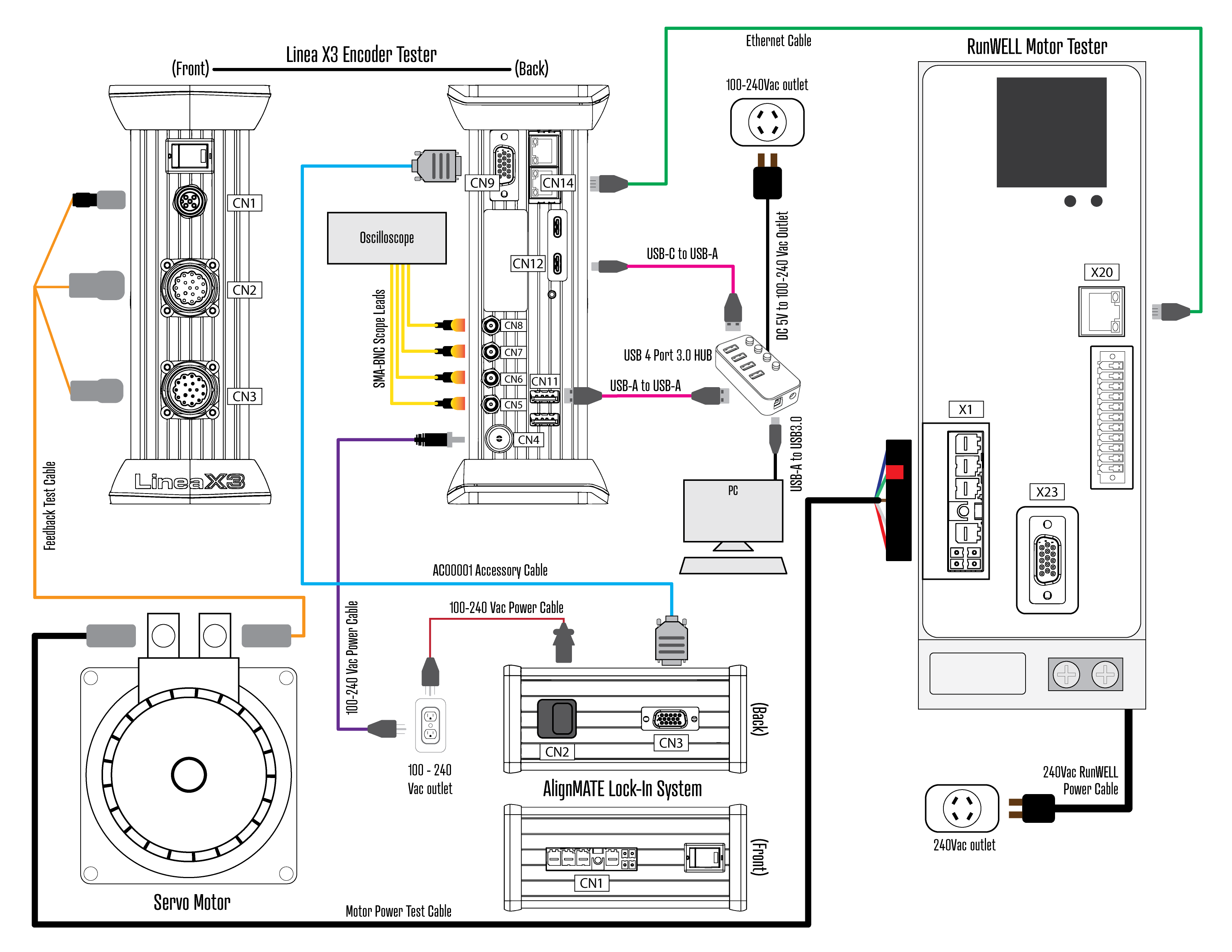
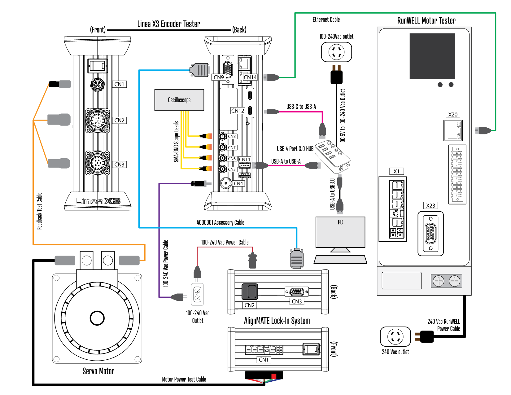
Now that we have the system requirements out of the way, let's discuss setup. We will start with the Linea X3. Connect USB-C to CN12 and USB-A to USB 4 Port 3.0 HUB. Plug the 100-240Vac Power Cable into CN4 and 100-240Vac Outlet.
If using an oscilloscope, we recommend [Tektronix TBS2104B]. Take the (4) SMA-BNC Scope Leads included with the kit. CN5 and CN6 are for Digital, and CN7 and CN8 are for Analog.
I have a Fanuc ais xx/xxxx-B with ai-B pulse coder in front of me. So, let's grab F00001-FA-AIB-JN2-SER and M00001-FA-A-1810-BK0. Test cables are available online and can be purchased directly from OctavaEngineering.com. Filter by Brand Compatibility, Connector Style, Feedback Technology, and Motor Model to quickly find the necessary feedback and motor power cable. Alternatively, build your own. You will have access from AutoCUE to our Test Cable Build Sheet Library. Each lists pinout, build instructions, and parts sourcing.
Connect the Feedback Test Cable to CN1 Encoder Power, CN2 Digital, and CN3 Analog. Not all encoders use analog, so don't worry if the Test Cable you have is without. The opposite end of the Feedback Test Cable connects directly to the encoder to be tested.
AlignMATE
Take the 100-240Vac Power Cable you were given. Connect it to CN2 and plug the adapter into a 100-240Vac Outlet. Then, take the AC00001 Accessory Cable and connect it to CN9 and CN3.
When performing alignments, connect the Motor Power Test Cable to CN1. The opposite end connects to the servo motor. The Fanuc αis I'm using today has a built-in brake.
Ahora vamos a configurar el RunWELL.
RunWELL
For Evaluation Mode, Run Mode, and Final Test, connect the Motor Power Test Cable to X1 and fasten the ground lead. Connect the opposite end of the Motor Power Test Cable to the motor. Take your Ethernet Network Cable and connect it to X20 and CN14. Unlike the Linea X3 and AlignMATE, the RunWELL uses 240Vac single-phase or three-phase. Connect 240Vac RunWELL Power Cable to 240Vac Outlet.
It is time to power everything up. Turn the SW1 Power Switch ON. Next, download and install AutoCUE Horizon Complete Installer [AHCI].
Instalación del software
The software is downloaded from OctavaEngineering.com. The content is password protected, so you will be prompted to log in to your OE Account. If you forget, click "Forget your password?" and we will send reset instructions.
Download AutoCUE Horizon Complete Installer
Introduction to AutoCUE
After installing the software and confirming the correct setup, watch this 20-minute video to familiarize yourself with AutoCUE.
Of course, we are here to help if you hit any snags. When you finish the video, move on to the AutoCUE Learning Series to familiarize yourself with the various types of servo motors. Remember, each purchase includes 12-hour complimentary training. For best results, we recommend a 4-hour virtual session to discuss test procedures and best practices followed by a 1-day in-person session at our facility or yours.